Posted on Monday, May 23, 2011 • Category:
Power Supplies
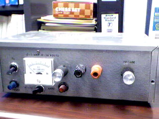
The linear laboratory power supply, shown in the schematic, provides 0-30 volts, at 1 amp current, using a discrete transistor regulator with op-amp feedback to control the output voltage. The supply was constructed in 1975 and has a constant current mode that can be used to recharge batteries. With reference to the schematic, lamp, LP2, is a power-on indicator. The other lamp (lower) lights when the unit reaches its preset current limit. R5, C2, and Q10 (TO-3 case) operate as a capacitor multiplier. The 36 volt zener across C2 limits the maximum supply voltage to the op-amps supply pins. D5, C4, C5, R15, and R16 provide a small amount of negative supply for the op-amps so that the op-amps can operate down to zero volts at the output pins (pins 6). A more modern design might eliminate these 4 components and use a CMOS rail-to-rail op-amp. Current limit is set by R3, D1, R4, R6, Q12, R10, and R13 providing a bias to U2 that partially turns off transistors Q9 and Q11 when the current limit is reached. R4 is a front panel potentiometer that sets the current limit, R22 is a front panel potentiometer that sets the output voltage (0-30 volts), and R11 is an internal trim-pot for calibration. The meter is a 1 milliamp meter with an internal resistance of 40 ohms. Switch S1 determines whether the meter reads 0-30 volts, or 0-1 amp.
 DIY Power Supply for Home Server Variable Laboratory DC Power Supply LM317 Constant Current Source Circuit Design Adjustable Bench Power Supply Adjustable Bench Power Supply Repairing Switching Power Supply TPS54232 Constant Current Source 13.8V 10A Power Supply 13.8V, 40A Switching Power Supply 3.3V and 5V Power Supply
Circuit-Zone.com © 2007-2024. All Rights Reserved.